 Building design can significantly impact energy efficiency and can result in substantial reductions in operating costs over the lifecycle of a building. To achieve these benefits, new software tools are being developed that help designers and building architects to model building performance at the critical design stage. Design changes can be readily evaluated prior to construction for performance efficiency. EcoDesigner is a next generation design tool that brings energy efficiency to the forefront of architectural design.
Let ”Green” Become an Organic Part of the Architectural Design Workflow
Approximately 80% of the design decisions that influence a building’s energy performance are made by the architect in the early design phase; the remaining 20% are made by engineers at the later phases of design. Earlier energy modeler software programs were targeted exclusively at energy experts who typically joined the design process at the end of the development phase.
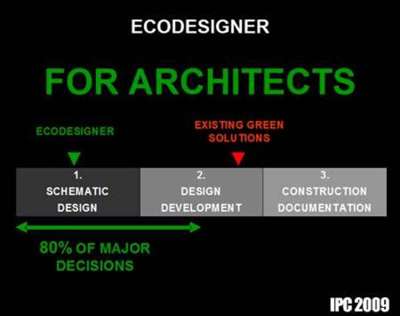 By that point, most important design decisions – including zoning, orientation, floor plan layout, lighting, MEP system types – were already made. Thus, the results of the energy experts’ evaluation had limited effect on the project. Apart from some minor adjustments, the original design concept remained intact whether it was ecologically suitable or not.
Today, increasing ecological awareness in every sphere of human activity, including the construction industry, has spurred the development of a more effective design tool: one that can be applied on projects of any size at the schematic design phase, enabling design concepts that are ecologically sound from their very foundations, not just as an additional feature.
Investors worldwide appreciate the value and financial sense of developing a truly green design, and architects who actively make ‘green’ decisions early on are saving their clients real money, in both the short and long term. Research on contemporary architectural design practices confirms that architects need a quick, reliable energy performance evaluation tool at the earliest stages of the design process.
Putting the Virtual Building at the Heart of Energy Analysis
Traditionally, building energy modeling software programs could be used effectively only by experts in building services. This expert-level energy evaluation was carried out as an isolated process that was not integrated into the rest of the design activity. Such software solutions demanded input of detailed data that was typically unavailable at the schematic design phase.
Another major disadvantage of these programs was that gathering and inputting the massive amounts of volume and surface data was an extremely tedious and time-consuming activity. If done without the aid of automation, the process was bound to be rife with errors, and the accuracy of the resulting database did not meet the standards set by the rest of the application.
The Graphisoft Custom Solutions team embarked upon developing a whole new approach to energy evaluation. Our top priorities were to break free from these ineffective conventions, to minimize and simplify user input, and to provide a continuous, highly automated workflow.
The result of our work is Graphisoft EcoDesigner, an application that allows architects to perform reliable energy evaluation of their Virtual Building within ArchiCAD. Due to the automatic structure geometry analysis algorithm, the evaluation process requires relatively few, simple and straightforward user inputs. A certified calculation engine performs dynamic building energy evaluation, providing information on the project’s yearly energy consumption, carbon footprint and monthly energy balance.
With EcoDesigner, the ArchiCAD Virtual Building becomes an even more intelligent “BIM” model. The program provides easy access to much-needed energy information concerning architectural projects in the early design phase, when changes are easy to effectuate, as opposed to detailed analysis at a stage when the design is well advanced and decisions have already been made.
This product is not a high-end energy calculation software; it does not produce accredited energy analysis output suitable for official documentation according to local codes and code ratings. The Export function button, available within EcoDesigner, activates the Export to VIP Energy dialog box, which enables the user to save all calculation input data in VIP Energy input file format. The saved file can then be opened using the StruSoft VIP-Energy software for detailed energy analysis of the designed building.
EcoDesigner is available for two platforms: Windows version for computers running Windows XP or Vista, and MacOS version for MacIntel computers running Mac OSX 10.4 or higher.
Real-Time Evaluation of Design Alternatives in the Conceptual Design Phase
“Sustainable architecture” is the practice of designing, constructing and maintaining buildings in a way that minimizes their environmental impact. A key aspect of sustainable design is energy efficiency: the attempt to reduce the amount of energy a building consumes over its life-span.
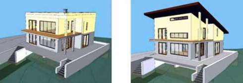
Relationships between building volumes, proposed area and orientation of glazed surfaces, as well as the properties of shading, all greatly influence energy consumption. Selecting the right alternative, which delivers better energy performance, is vital for developing a successful project that lives up to current and future standards.
 EcoDesigner is optimized to help architects evaluate energy efficiency and compare early design variations based on yearly energy consumption, carbon footprint and monthly energy balance. Real-Time Virtual Building Model Energy Evaluation
To bring the energy evaluation module closer to the CAD modeler software, EcoDesigner has been developed as a direct add-on application to the popular Graphisoft ArchiCAD 12. The simple yet effective three-step workflow of the program (Analyze > Calculate > Results) makes energy evaluation a task that is as easy as generating a section or a 3D view from the Virtual Building model.
BIM Geometry Analysis
The basis of the energy evaluation is the Virtual Building model created by the architect in ArchiCAD for the usual purposes: client presentati ons or design documentation. However, while the aforementioned conventional methods of energy evaluation usually require some sort of data export or mapping, EcoDesigner works directly within the CAD software – this minimizes data loss or distortion along the way, and maximizes calculation accuracy. Energy balance evaluation can be carried out on the full model, or only a selected part of it – just select the desired area using the marquee tool.
When launched, EcoDesigner activates the automatic structure mark-up function that selects and groups structures based on their relevance in energy calculations. For easier identification, the marked-up structures are differentiated by color on the floor plans and in the 3D view according to their types: internal structures, roofs, external walls, floors on ground, basement walls and basement floors.
Since such analysis and grouping of building structures is often a complex and intricate task, human judgment may override the computer-generated selection sets: the analysis can be adjusted manually. EcoDesigner’s user-friendly floating palette enables the user to fine-tune the structure markup made by the program.
After the selection sets are approved by the user, the necessary geometric data of the marked up structures (orientation, CAD element type and fill, surface area, volume and thickness) and the building itself (building volume and tempered floor area) are acquired by the computer and displayed on the Building shell elements list of the Structures tab page of EcoDesigner.
Discussion Between Architect and Project Energetics – the EcoDesigner Dialog
The EcoDesigner four-tab-page dialog box serves two purposes: it allows users to provide input needed to complete the energy evaluation; and it displays the lists of data obtained by the model analysis described above.
Project Location and Function
On the first tab page, entitled Location and Function, project location is given by geographical coordinates and a custom name. Using the geographical coordinates and the time zone provided, the program obtains relevant weather data (air temperature, relative humidity, wind speed and solar radiance hourly values for one reference year) from an online weather database, or, in case of cities present in ArchiCAD by default, from the database within EcoDesigner. Once the weather data has been downloaded, it is stored within the application, so internet connection is only needed the first time a certain project is evaluated.
The editable project orientation provides direct access to the Project North settings of the BIM model from within the energy evaluation application. Based on the Project North defined here, EcoDesigner recognizes eight different orientations (North-West, West, South-West etc.) and uses these to evaluate the building structure.
The numeric input entered at the Grade level to project zero setting, together with the Underground insulation settings provided at the Structures tab page, enable the program to correctly evaluate linear thermal currents. Building structures that are in direct contact with the ground are evaluated using a different algorithm, since linear heat loss is far more significant than surface-related heat loss in these structures.
While other energetic modeler programs require numeric input, EcoDesigner prefers linking numeric data to easily understandable terms, to enhance usability. Settings such as wind protection and the rate of solar reflection from surrounding surfaces illustrate this approach: the user just selects a predefined option from the dropdown menus.
There are two different ways to define shading properties of the Virtual Building within EcoDesigner. Vertical and horizontal edges of external objects, or projecting parts of the building envelope itself, cast shadows on the elevations. For each building orientation, the user chooses applicable Shading and Complexity settings, under the Façade shading option of the Location and Function tab page. The user may assign various shading devices to openings on the building shell. This is done on the Openings tab page.
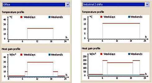
In order to carry out a successful energy evaluation, the primary function of the building must be defined. Required hourly internal temperature data and internal heat gains (from humans, lighting, equipment and hot water generation) are linked to each predefined building activity type (offices, residential buildings, schools, hospitals, food services, retail, various industries, performance spaces and parking/service areas) within EcoDesigner. The program enables the evaluation of multi-functional buildings as well. It is possible to combine up to three different building functions within a single project quickly, as the matching package of extensive background information is attached to each activity, and graphs illustrate the performance data in a user-friendly manner.
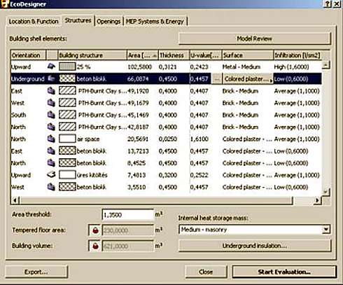
Relevant Building Structures
The Structures tab page displays geometric data – obtained by the BIM Geometry Analysis – for the whole building (tempered volume and floor area), as well as data for selected structures.
Besides orientation, CAD element type, fill type, surface area and skin thickness, the Building shell elements list contains additional relevant physical properties (heat transmission coefficient, surface type and infiltration rate). These properties must be assigned by the architect using the U-value calculator, which can be accessed from the Building shell elements list.
The U-value calculator enables the user to ‘build up’ composite structures by selecting items from the material catalog included in the program. This catalog lists numerous building materials with their thermal conductivity, density and heat capacity values. Static heat transmission coefficients of external building envelope structures, after being further modified according to the thermal bridge effect of construction details, are automatically displayed on the U-value calculator panel. The calculation engine eventually uses the geometry data and the assigned physical properties of the composite skin orders for dynamic temperature drop calculation and determines the resultant U-values for every hour of the year.
Depending on local convention, some users may prefer to use the R value (Thermal Resistance Coefficient), which is the inverse of the U value, therefore listing and displaying R values instead of U values is possible both on the dialog and in the final Evaluation Report.
The Structures tab page also contains the Internal heat storage mass (heavy, medium or lightweight) and Underground insulation settings needed to evaluate linear thermal currents in building structures that are in direct contact with the ground.
The Model review function button enables the architect to leave EcoDesigner temporarily, without closing it, to change the building model or to alter the previously defined structure markups, and thus to modify the structure selection sets.
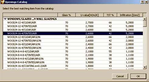
Openings on the Building Shell
This tab page lists geometric data of openings (orientation, CAD opening type and surface area) obtained by the BIM Geometry Analysis. Additional relevant physical properties (glazing percentage, U-value, solar transmittance and infiltration rate) are assigned by the user by selecting products from the built-in Opening catalog. Manual data entry is also possible, if specific product properties are already available at the time of the evaluation.
Shading devices may also be attached to each entry of the list separately, by selecting one of the predefined types: curtains, venetian blinds, roller blinds, awnings, external blinds, external adjustable louvers, or shutters. EcoDesigner’s dynamic evaluation takes into account the fact that some shading devices are only activated when needed, that is, when the temperature and/or solar radiation inside become too high. Furthermore, external shading devices become ineffective if the windspeed exceeds the threshold value specified for the applied product.
MEP Systems and Energy Settings
The energy balance evaluation requires some basic user input concerning the MEP systems to be installed in the planned building. On this tab page, the user must define the proposed cooling and ventilation type, and may also define additional devices such as air-to-air energy recovery systems, heat pumps and solar panels.
If the user enters additional local data such as currency and used energy type into the Energy sources and costs dialog box, then EcoDesigner also estimates the project’s carbon footprint and energy costs.
The Calculation Engine
Once all necessary input data is obtained, EcoDesigner provides it to the VIPCore Calculation Engine as an XML file. The engine then performs the dynamic energy evaluation and sends the results back to EcoDesigner in XML format.
The calculation engine relies entirely on dynamic models, in which every model is broken down to a level at which facts and behavior are known. The calculation is repeated every hour. The accuracy of each model has been validated and verified against real buildings.
When calculating a building’s energy consumption, the program utilizes known or measured facts about all parts of the energy flow. The energy flow is calculated taking climate factors (temperature, sun, humidity and wind) into consideration. Other factors in the calculation include the varying room temperature requirements, air exchange, internal heat gains, and the use of solar panels, ventilation units, heat pumps and cooling systems. The program calculates the energy balance of the building by comparing the emitted energy (cooling,ventilation, infiltration, transmission) with the supplied energy (heating, solar irradiation, heat recovery, internal heat gain and electricity).
EcoDesigner uses the same simulation kernel as the VIP Energy product, which is validated with the following tests (listed in order of complexity):
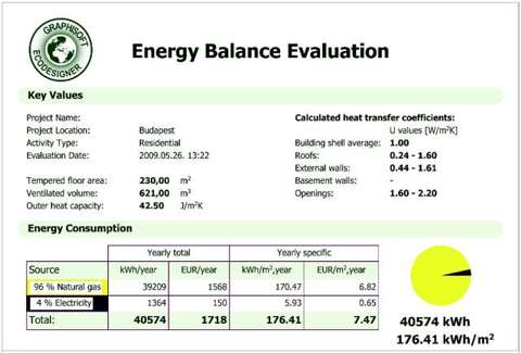
Energy Balance Evaluation Report
The EcoDesigner Energy Balance Evaluation sheet may be printed or saved in PDF format.
The Evaluation sheet’s Key Values section displays the evaluation date, and basic information such as project name, location and activity type, as specified by the user on the first tab page of the EcoDesigner dialog box.The total tempered floor area and ventilated building volume values are also listed here, along with the outer heat capacity of the building shell.
Outer heat capacity measures the capacity of building structures to store heat against changing outside air temperature: that is, the resistance close to the surface that helps to reduces energy fluctuations through the structure. Also in the Key Values section, the minimum and maximum average heat transfer coefficient values of roofs, external walls, basement walls and openings are displayed, as determined by the U-value calculator.
The Energy Consumption pie chart graphically displays the percentages of used energy sources (gas, propane, oil, wood, coal or electricity), alongside a table listing the annual total and specific quantity and price of each energy source consumed.
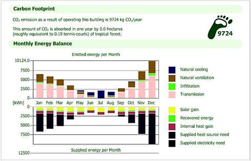
The Carbon Footprint index provides information on the carbon dioxide emissions resulting from operating the building over the course of a year. The area of tropical forest required to absorb this carbon dioxide quantity is also displayed for comparison.
The Monthly Energy Balance bar chart is a graphical display of the amount of energy the building emits (top part of chart), as well as the amount of energy it absorbs from the environment and its own internal heat sources (bottom part of chart). The Emitted energy and Supplied energy bars must be equal every month. The vertical axis of the chart shows an energy scale, while the horizontal axis shows the months of the year. To the right of the diagram, the components that make up the bars of the chart are listed. The number and type of these components depend on the data entered for the building’s MEP systems.
The EcoDesigner Advantage
EcoDesigner enables architects to differentiate themselves from the competition by offering their clients:
These can be key factors in winning new jobs in both the private and public sectors. At the same time, the “carbon footprint” consequences of designs highlight the importance of conserving nature’s resources.
———————————————————————————————
Miklos Sved – Architect – GRAPHISOFT EcoDesigner Product Manager
For more information about the Graphisoft EcoDesigner solution, including tutorial movies explaining the workflow, visit the official website at: www.graphisoft.com/products/archicad/solutions/ecodesigner.html
