 In Part 2 – Manual Reset, SmartGeometry 2010, Barcelona, Working Prototypes, architect Don Chong provides additional coverage of the event. He discusses industrial design, the details of sandstone and begins to lay out the concept of ‘Manual Reset’.
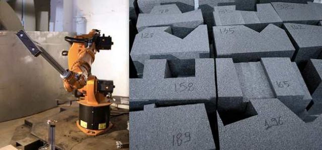
The basic proposition is to use sand as the primary base medium with an inorganic binding agent. It would take several hours (i.e. – not days or weeks) to ‘rapid-prototype’ a form. Only in this case, it’s more like ‘rapid-construct’. The material would cure into something closer to sandstone in touch and in appearance. This is a true case of file-to-finish.
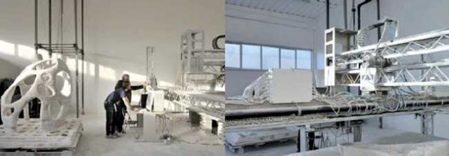
One has to wonder what this could mean. One has to wonder what seeds this has planted at the SmartGeometry conference alone. We may find ourselves a generation later to say, ‘I was actually there when Dini proposed this contraption as a new way to build…’ If it weren’t for his well-bespoke presence, you’d think he was of the ‘mad-scientist’ ilk.
The type that has a somewhat savant-quality to what they are doing. Incredibly enough, as if this were scripted, Dini’s point of inspiration is Gaudí. Dini’s own dream: to complete the final components of the Sagrada Familia with his 3D printer. The real conversation here, is that Dini’s technologies suddenly makes the construction of complex curvatures attainable. It would be only as difficult as preparing it digitally. And Dini’s probably as excited as ever to share the stage with the one person who may want to give him that opporunity in Mark Burry. Only at SmartGeometry…!
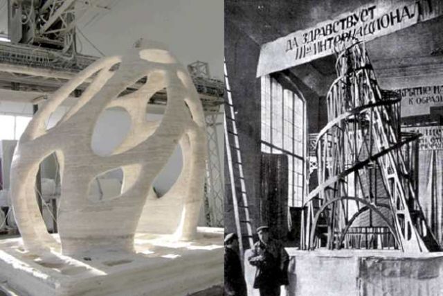
The scale of the project Dini is undertaking, and the ambition for more challenging geometries and surfaces, is akin to Vladimir Tatlin’s well-known model for a Russian monument for the ‘Third International’ – a proud design for a project aiming to reach higher than Paris’ Eiffel Tower with a helical, somewhat Babylonian structure. Interestingly, this project even unrealized captured the imagination of architects and historians alike.
My theory: Because it was effectively a built project that engaged fully with the structural concept, and became more prototype than merely model. It carried with it ideas that further enlightened other projects. It had value as a ‘test’ and, therefore, was a prototype (though scaled) for advancement in other areas.
Structurally expressive projects seem to benefit most from these ‘scaled prototypes’, which even the Sagrada Familia design teams would likely be able concur with.In any case, the prospect for a full-scale ‘output-architecture’ by Dini is fascinating, as odd or as new as it is to process in our minds and from what we have been accustomed to.
This ‘printed architecture’ would want to avoid any resemblance to the fumbled vision of Thomas Edison’s monolithically poured-in-place concrete house prototype – which was more absurd, than it was forward-thinking. (Here, it is a perfect example for why one should prototype; so you can decide against a proposition, too!).
A 3D-printed full-scale sandstone structure would need to understand what its relationship is to architecture vs. industrial design vs. sculpture. It’s making me realize that the latter two are generally fabricated in singular materials, or at least in dominant materials.
The idea for ‘craft’ would be hard to locate on projects that are monolithically ‘outputted’. Maybe ‘output-architecture’ signals the end of craft as we know it, however, maybe there are other areas to ‘craft’ the script, or to ‘craft’ the algorithms, or to ‘craft’ the medium’s response to the machines.
There would be area to control quality and tolerances, so perhaps there is still room for ‘craft’…I just wonder whether full-scale 3D ‘printing’ is more than having to provide an ‘easier’ option non-linear, curvaceous and therefore somewhat complex, surfaced forms, or is it all about the reduction of construction time and the nonrequirement for ‘assembled’, multiple-trade construction. For the record, it would be just as profound for me that a project could look ‘square’ or ‘straight’ so long as I knew that it could be ‘output’ with a material and care as some of the best work being ‘assembled’.
To really kick the tires on this technology as a legitimate means of construction, one would have to come to terms with the nature of materials. Or more bluntly, one would have to recognize that the nature of materials, their natural compressive limits or tensile limits – aspects that we equally embrace as we would be fearful of – may suddenly become incidental. And this could be disturbing from a purist’s understanding of construction and architecture as a series of applied assemblies, or it could be enlightening from a visionist’s hope for new form and easier modes of building. Either way, it may easily contribute to yet another well-earned, healthy and necessary paradigm shift in design and architecture.
Rolling Up Sleeves
This was a nice way to remind ourselves of the need to test things. A need to make prototypes, and to answer to the urge to see things in a real-time manner. It is this ability to register things in person, at our scale, and to test things as close to our hands as possible that makes this event for SmartGeometry 2010 that much more profound. It’s the reason why SmartGeometry incorporated the IaaC venue, and the IaaC culture into the bloodstream of this year’s conference.
And it was a natural fit, to be sure.It’s as if there was an urge to rekindle that which is always going to be a part of us. And it isn’t about clicking mice, or surface nodes onscreen, or beautifully scripted algorithms… it’s about getting down and dirty, and seeing if we could walk the talk. Or build the vision. Or make the sketch.
In this way, I got the feeling that this was a well-warranted and highly sought after moment for the SmartGeometry set… It was a way to engage, again, and to re-affirm that in the end we want to make and we want to build. And that we want to do it well. And we want to prove to ourselves that it’s still within us, and that we’re still good at it. It’s another fresh start. It is a ‘Manual Reset’.
Industrial Strength Design
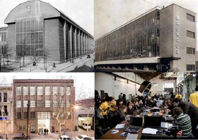
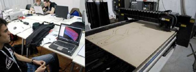
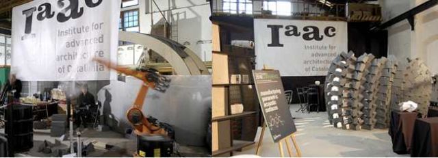
I have seen many schools of architecture form Helsinki to Halifax, from Ithaca to The Cooper Union, IIT in Chicago to the ETH in Zurich. I have also taught at the EPFL in Lausanne in Switzerland and taught out of a Dolf Schnebli-designed atélier… All top-notch institutions, with excellent environments for architectural education. I must say, however, that here in Barcelona the Institute for Advanced Architecture of Catalunia, or IaaC, is a one-of-kind marvel.
The fact that the building operates amongst multi-level spaces perched over the main hall in a repurposed urban factory surely would have something to do with the industrious undertones in all the work on the walls, the floor, the screens and the tables. IaaC generously contributed their space as the venue for the Workshop proceeding for ten clusters to investigate some of the key issues confronting their aspects of the AEC industry.
And IaaC together with SmartGeometry struck a beautiful chord, thanks in large part to director Marta Malé-Alemany – by allowing a parallel ‘back-of-house’ studio/shop space to test physical prototypes with IaaC’s world-renowned facilities for digital fabrication and architectural prototyping, an active environment that doesn’t lose its sights on architectural theory and sustainability. It’s the truest rendition – in factory form, I might add – for an architectural institutions’s endeavours toward building projects and ideas.
I can’t not think of Peter Behrens’ AEG Turbine factory in Berlin for its tough elegance, and for what that factory meant to a new generation of progressive architecture. It’s also easy to be reminded of the Bauhaus’ all-encompassing, handson pedagogical stance in architectural education in Germany, run by Walter Gropius (who interestingly worked with Peter Behrens). And wouldn’t this ‘tough elegance’ be the right match for the roll-up-your sleeves venue the for ‘first course’ of the SmartGeometry event? It was tactile, dirty and real-time. Full-scale and immediate.
The Ecole des BeauxArts (and their ‘charette’ deadlines) would be proud of the intensity, density and urgency generated here at the IaaC. The energy was palpable and infectious. Part lab, part garage – this was a high-energy place that was exacting as it was liberating. Yes, people were having fun.Equally enamouring, was the camaraderie and the exchange among the players.
And to see chunks of material flying, the clamouring of sheet metal, or the whizzing of a robot. Interestingly enough, while prototypes are the mainstay of activity within the IaaC (and certainly for the SmartGeometry proceedings this year), it would be safe to say that IaaC is following the lineage of architectural institutions who in themselves are prototypes for a pedagogy of making…
Design to Destruction
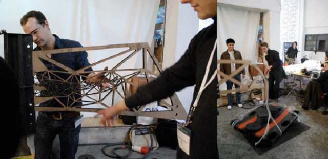
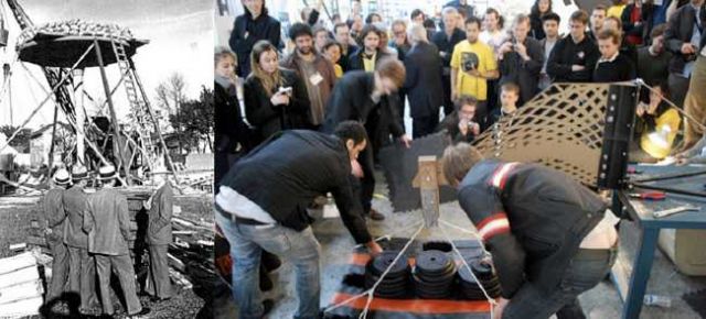
It makes for good drama when the tension in the room has as much to do with biting fingernails as it would with the opposing force to the compressive strength in structural members. Of all the ten clusters espousing to experiment with the aid of sophisticated computer technology and parametric software, the ‘Design to Destruction’ group gets the nod for the most spirited. Cheers would be preceded by thuds and crashes. Who knew that computational design enthusiasts would take such joy, and ostensible learning, from the performance or, more precisely, the lack thereof – for the proposed structural cantilevered members?
In a carnival-like atmosphere lacking only the megaphones and stuffed animals, crowds would gather to witness a lineup of CNC-milled 3/4″ thk. (19 mm) plywood sheets about 4′ (1200 mm) in length perched into a standard moment connection; each proposed member would be subjected to graduated weight increases hanging off their extreme points.
The aim was to see whose prototype piece could provide the lightest component to withstand the greatest load. It was through the use of Bentley’s GenerativeComponents software that the cluster participants would devise various custom trusses prior to have them lasercut.
The natural takeaway was the live performance of design – by way of parametric analyses and optimizations – that the various collaborators were able to study and learn from. It was truly a hands-on effort, and one where architects and engineers were able to converge. The various open web combinations showed patterns ranging between Vierendeel truss patterns, to catenaries and to anthropomorphic patterns.
Even the forensic examination of the split-lines of the broken cantilevered members would prove to be as engaging as the fresh, untested pieces. Led by Sam Joyce and Al Fisher of Buro Happold’s SMART Group, the cluster was emblematic of SmartGeometry’s pursuit for a real-life, tactile experience and evaluative process.
I certainly hope the participants were able to judge the fine balance between rational behaviour and resistances with the pursuit of visually-pleasing forms. Real design, for me anyway, rests neatly in the subtle balances of the rational and the expressive – and this cluster demonstrated that beautifully. I couldn’t resist thinking about Frank Lloyd Wright’s weight test – yes, his own voluntary ‘Design to Destruction’ test – of his proposed concrete ‘lily pad’ column at Racine, Wisconsin for the Johnson Wax Center.
In a show of defiance, Wright insisted on laying sandbag after sandbag on a sample column well beyond the required capacity to demonstrate to his nay-sayers just how well-equipped his new concrete prototypes would be. Like this year’s SmartGeometry events, never had destruction been been so delightful.
Upon further thinking, I realized also the convergence of expression and efficacy. It seems to be a shared holy grail where the architect’s intent neatly overlaps with the engineer’s intent – where elegance in design might simply be about the beauty and the performance of the structure in question.
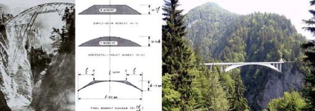
For me, this takes us to the mountains in Schiers, Switzerland in 1929. It is the moment in which Modernism in architecture had a pivotal moment and where reinforced concrete in its honest and naked state truly had its coming-out party. This was at least as significant as Auguste Perret’s seminal 25 Rue Franklin in Paris, in which Perret built an infill apartment structure with a decidedly clear expression of the reinforced concrete slab structure. It was unheard of at the time to express concrete, though satisfyingly beautiful in its outcome.
And it ushered in a new era together with his contemporary Robert Maillart, who had won the design for the Salginatobelbrücke in Schiers, Switzerland. It remains to be seen whether Maillart’s proposal being the cheapest out of the 19 submissions was the sole reason for it winning, or if it was the have-your-cake-and-eat-it-too condition of being the most cost-effective and the most-beautiful solution.
Having seen this bridge in person, you truly understand how being lightweight and high-performance is the preferred option being so high up and so remote. What a way to show how engineering, construction and design can conspire so beautifully together! And with two opposing cantilevered components springing from opposing mountain faces, both trying to be as light as possible and as strong as possible, it comes right back to the core objectives of the archetypal scaled-down structural prototypes here in Barcelona.
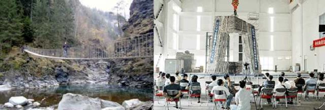
I applaud this cluster for getting up close and personal with their designs, and for positioning their experiments directly to simple, relevant and real challenges shared by engineers and architects across several generations. Something we have seen in reductive designs for Swiss footbridges like Jürg Conzett sparingly creates, or what Arup’s Cecil Balmond would have thoroughly tested in the double-cantilevering CCTV in Beijing.
Explicit Bricks It should have come as no surprise for me to have spotted a ‘Kuka’ robot in the IaaC space. In keeping with the noholds-barred intensive charette-style workshop sessions, we found something akin to the people’s award winner for ‘Breakout Performance’. It was the animated and highly personified presence of the ‘arm’ – the same one we see in the automotive industry assembly lines, only this one was fueled by data based on algorithms and scripting provided by GenerativeComponents.
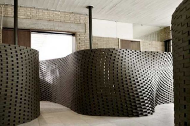
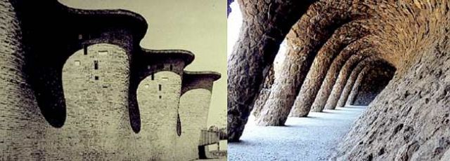
What I liked about this cluster’s approach, led by Tobias Bonwetsch and Ralph Bertschi of the ETH in Zurich, was the interest in tackling a common yet sometimes complex condition in architecture: namely, the curving block wall. Better still, the approach here was to see how the Kuka machine would handle each polyurethane block: from the precise and individual shaping of each unit – and – to the laying and interlocking of each unit in their final built position.
The fabrication of each unit was simple; it was to take each polyurethane block and so the Kuka would manoeuvre the virgin block across a stationary hot-wire foam cutter. Using this process, an elegant series of slightly shifting mortise and tenons were shaped with surprisingly crisp dexterity. The loose dovetail look of the pieces suggested a flow of cuts that appeared to be cognizant of the fact that the angle of the receiving unit would want to respect the angle of the incoming unit, as well as the basic load of holding itself up in place.
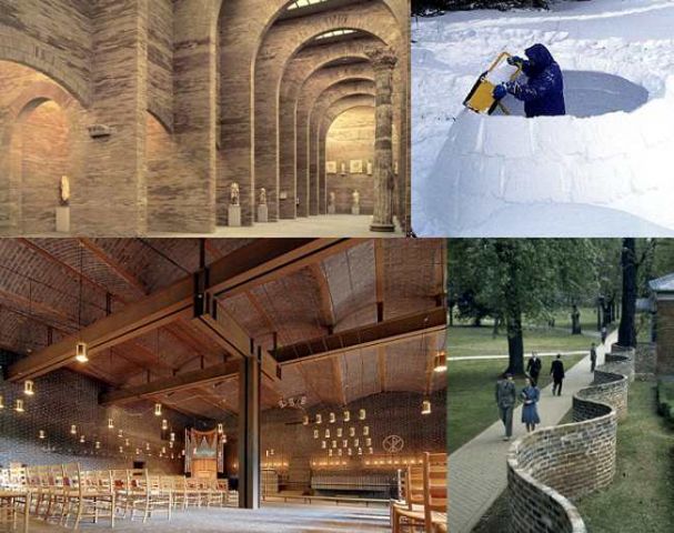
What comes to mind is the simple igloo, and the human scaled erection of the surrounding walls of carved blocks. The maker would have to recognize somewhat intuitively the changing inner cuts as the helical positioning helps to secure the previously laid blocks. Its a profoundly simple process, but one that understands the angles of insertion and the angles of gravity being distributed. Explicit Bricks does a fine job in its quest to seek a more complex curve and for, quite frankly, trying. Kudos to the Kuka and its team for attempting to do this. It should be stated off the bat, that the blocks had to eventually be erected manually by the human team members.
Though one wonders whether two Kuka’s – one to hold the receiving unit firmly and delicately in place and one to slide the next one in – might actually be the difference in making it a complete file-to-output fabrication.A deeper look into the ETH reveals that the inspiration from Bonwetsch and Bertschi’s indeed comes from their prior involvement with compatriots Fabio Gramazio and Matthias Kohler, who spearheaded the used robotic techniques for Switerland’s sinuously elegant Venice Biennale pavilion made up of – in this case – uniform modular brick, but arranged in a refreshingly voluptuous, un-Swiss-like manner. Back here at the IAAC space, we see an attempt by Bonwetsch and Bertshchi’s cluster team to introduce the added complexity of uniquely fabricated individual units. Again, something to be applauded at least for the brevity of the complex singular pieces…
In any case, as a working prototype, I find Explicit Bricks to be highly engaging. You want this cluster to try harder and finetune their application. And you really want to see this project evolve towards the next SmartGeometry (if we are so lucky to have this Working Prototypes shop become an annual fixture) so we can see what the cluster might have learned along the way or, really, how their prototypes have improved.
The other instances for such sophistication in masonry units include projects such as Thomas Jefferson’s serpentine garden walls at the University of Virginia. Here we see the need to provide curving walls to allow a thin (single wythe) brick wall to support itself by resisting any possibility of tipping over. And advanced application of this, perhaps with the Explicit Bricks approach, could be to have a wider array of radially cut masonry units for a wider array of curved walls. Even if it would be unrealistic to gear up a few Kukas on site, the mere ability to number and sequence the brick would be a significant timesaver and assurance in structural integrity that would make this application a veritable gamechanger.
And I emphasize the structural aspect of it, since we know fabrication of non-orthographic planes and walls is nothing new. But the ability to create shapes which allow for more ‘fitted’ and ‘unique’ interlocking, and that which respects the dynamics of structural load is something I think is a more of an interesting prospect on how parametrics can dovetail – no pun intended – with the world of curved masonry walls in the construction industry.Rafael Moneo’s modern take on roman arches employs different shaped bricks for concentric layerings of arched soldier courses at the National Museum of Roman Art in Spain.
The calculations to cut the individual bricks would be simple enough to determine since these are pure radius-based arches. But what about parabolic arches, or splined arches? As long as the structural loads would be designed accordingly, could a process shown by the Explicit Bricks team show how arches might be able to be shaped – then perhaps pre-fabricated into a complete arch – then erected onto site? We can turn to the elegance and boldness of the work of Sigurd Lewerentz’s St. Petri Church in Sweden which employs beautiful arches with masonry units in rare, full view. Or Eladio Dieste’s triumphant undulating masonry walls of the Cristo Obrero Church in Uruguay.
And, to come full circle, why not back to Gaudí himself at Park Guell? Imagine where Gaudí could have taken technologies like this, to assist in what he already laboured on. To include a parametrically constructed solution using technologies like the Kuka robot surely would have to be inspired, in the very least, by advanced masonry projects already created manually decades perhaps centuries earlier.
Clearly, we’ve managed to make highly sophisticated things – without the benefit of such widely availability and refinement in software like GenerativeComponents and in tools like a Kuka robot. But maybe we now can, and maybe we now should. It may be the stuff of dreams, but is this dream closer to reality than we think? I’d like to think this year’s SmartGeometry would say it is indeed closer to reality.At this point, I would be remiss to state at least some angle on this human urge for curving or undulating forms. This indeed would make a longer discussion, but perhaps key point is that we, as a civilization, may want to express in our built identity aspects of nature. And, in a way that wouldn’t be nostalgic so much as necessary.
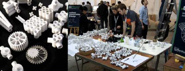
This makes a good lead into our next cluster…Nonlinear Systems Biology and Design This particular workshop engaged in the ongoing interests of Jenny Sabin and Peter Lloyd Jones. Their thesis appears to be more interested in exploring the natural world to glean, by models or by inspiration, possible references to adaptive, modular, flexible and layered systems. And from here, these attributes would form the analog lexicon in which to integrate structural component systems, or specific joinery details, which would provide a refreshingly new architectural complexities founded by principles in natural, even biological, conditions. And all this with to be applied for more ‘complex’, non-linear architectural possibilities.
What I like about this, is it doesn’t attempt to take a superficial ‘mimicry’ approach, which is always at risk at missing the point entirely by using imagery as the sole associative attribute to nature. This cluster’s prototypes explored rapidprototyping of joints which for me was of greater interest, and what I regard as the real fruits of their labours – whereas the resulting forms were more a convincing demonstration using in aggregate the component pieces generated.
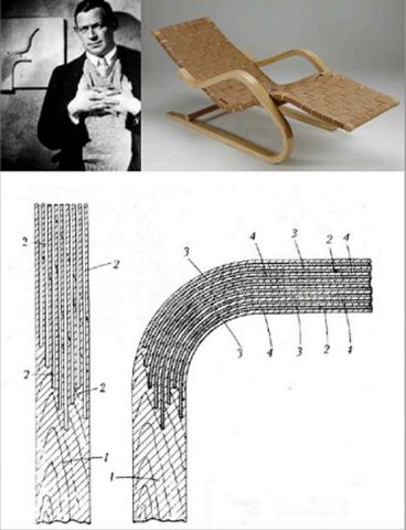
The cluster’s display of fabricated pieces makes some satisfying associations historically with design that is interested in the syntax of joints. Whether it is with Charles and Ray Eames perfecting their aluminum group chairs by way of their hinge, moment and fixed component joints; or Alvar Aalto and his proud discovery of the slip-jointed, structurally integral and flexible fingered joints in plywood – the clusters targeted area of interest seems to be a worthy, if not necessary, approach in design.
And that is to consider the integration of ‘process and component pieces’ in order to stage a natural, systematic way to construct larger perhaps unknown, indeterminate forms. That’s the kicker for me, and that’s what I like the tenor of the studio: it seems as interested to extract the essence and dynamic relationships in nature, as a the only real analog worth studying. This way, one can create a morphology and typology of designed joints (that show adaptive and evolving adjustments) depending on the criteria and conditions between the more regularized members.
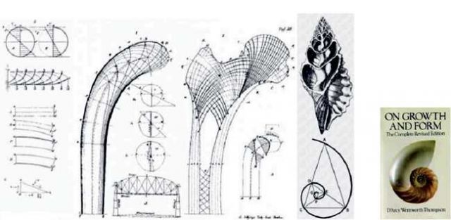
Take D’Arcy Wentworth Thompson’s seminal 1917 book On Growth and Form. It revealed in thorough form what people have intuited but never had seen as clearly until its publication. That is, that nature has taken millennia to develop the most dynamic and efficient structures in animals and in plants, so it was long overdue that we as a civiliaztion took notice. And it would be here, that generations of architects and engineers have already sought further, more explicit, inspiration by way of new patterns in mathematics, structure or growth formation. Here we see Thompson studying patterns that show resilience in form and in particular jointed conditions.With Sabin and Jones’ cluster, and their deeper work and studies, we can see once again how nature has always been available as a springboard to further our own interests in the built environment. It was noticeably exacting and fluid in how the participants took a measured approach for what would be a highly intuitive level of building. I think that is a highly sustainable and progressive attitude towards construction and, maybe more so, towards design.
—————————————————————————–
Part 1 of this article is available.
Part 3 of this article is available.
Don Chong is a V1 Magazine columnist and architect based in Toronto, Canada. His work and studio information are available at www.donaldchongstudio.com
